Advanced automation
Techpol Srl can claim to be one of the few companies implementing really industry 4.0.
The Techpol Automation department can count on his own design department.
The automation is studied on the basis of customer specifications, with the aim of facilitating the work of the operators as much as possible and of maximizing the return on investment. The project is carried out using specific software such as "Solidworks", "Creo" or "Catia".
During the design phase, simulations are carried out to verify possible problems.At the same time, the wiring diagram and the software program of our automation are created.
Even the heavy carpentry of our automations is welded and made internally. When the frame has been built, the operators take care of the machine board by wiring all the electrical and pneumatic components.
Then we proceed to the final test: the software programmer and the mechanical designer carry out the first test in the workshop. When the machine is compliant it is taken to the department.
Techpol has equipped itself with an automatic vertical warehousewith sliding shelves for a reduction in times and errors in picking up the material, maximum protection of the stored material and efficient management of spare parts and components for service and for new machines.
To meet production requirements, Techpol is able to produce the following types of equipment internally:
Automation and auxiliary components to molding machines
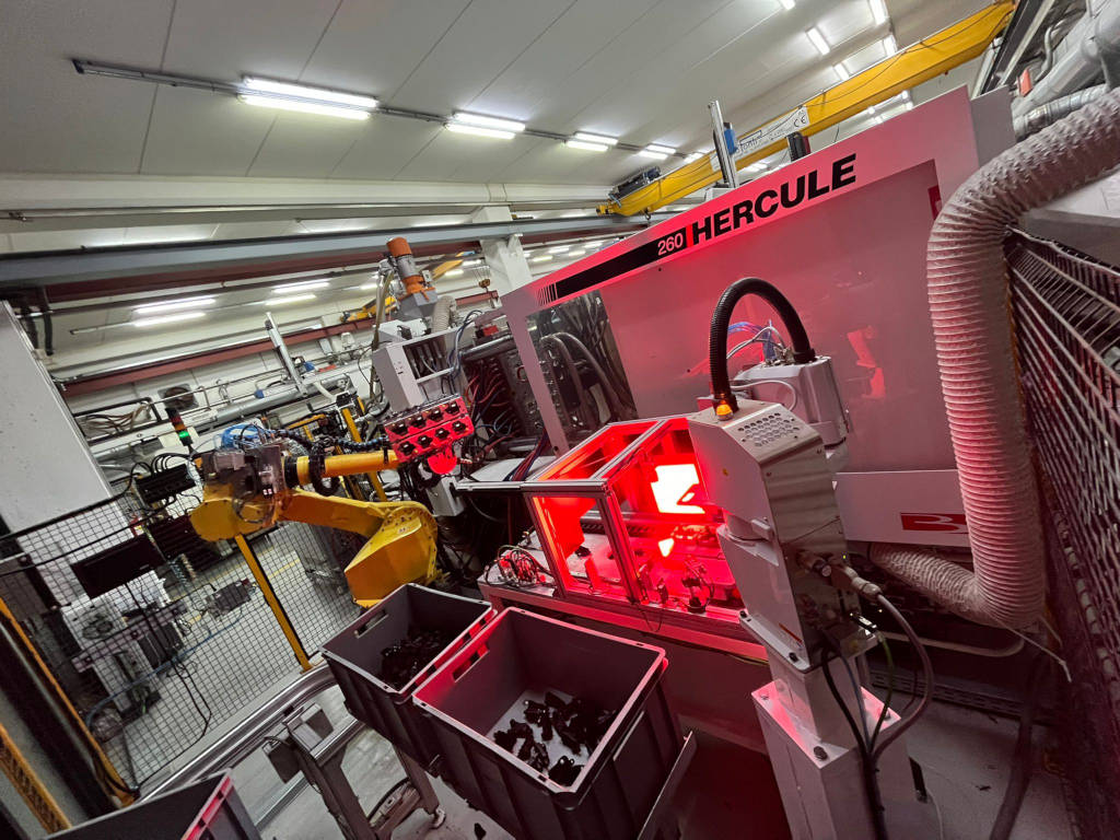
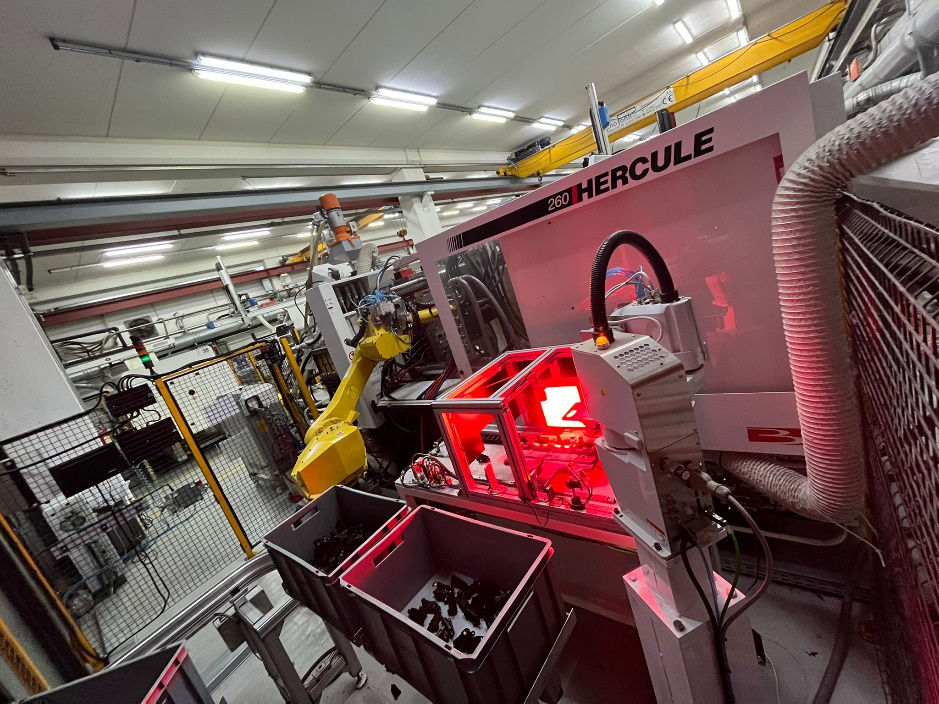
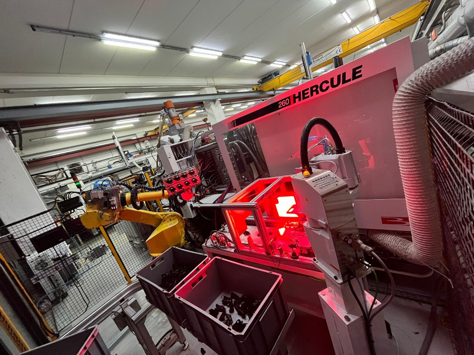
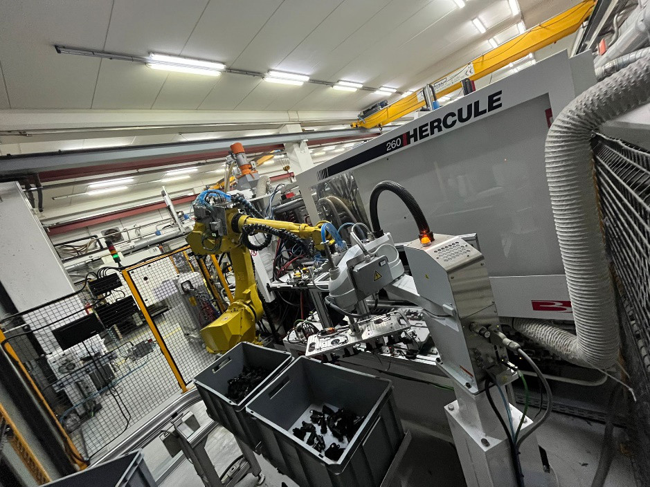
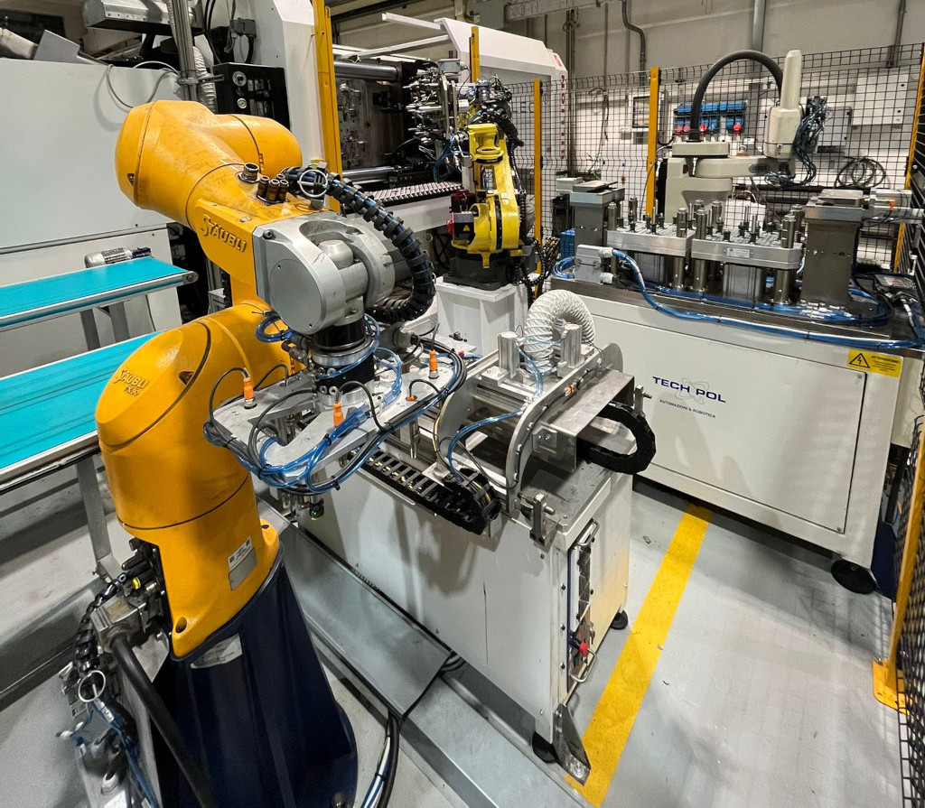
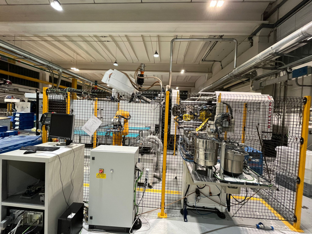
- Integration of anthropomorphic robots and auxiliary machines such as sprue cutter, o-ring assembly, feeding of metal inserts for over-molding, post-molding assembly of bushings, screws and o-rings, laser marking, control of the presence of accessories with sensors or vision.
- Handling with anthropomorphic robot and scara robot.
- Gripping hand
Automatic and semi-automatic work station
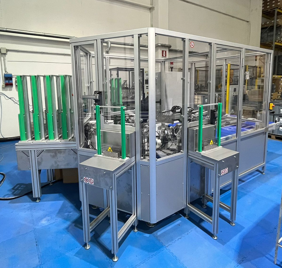
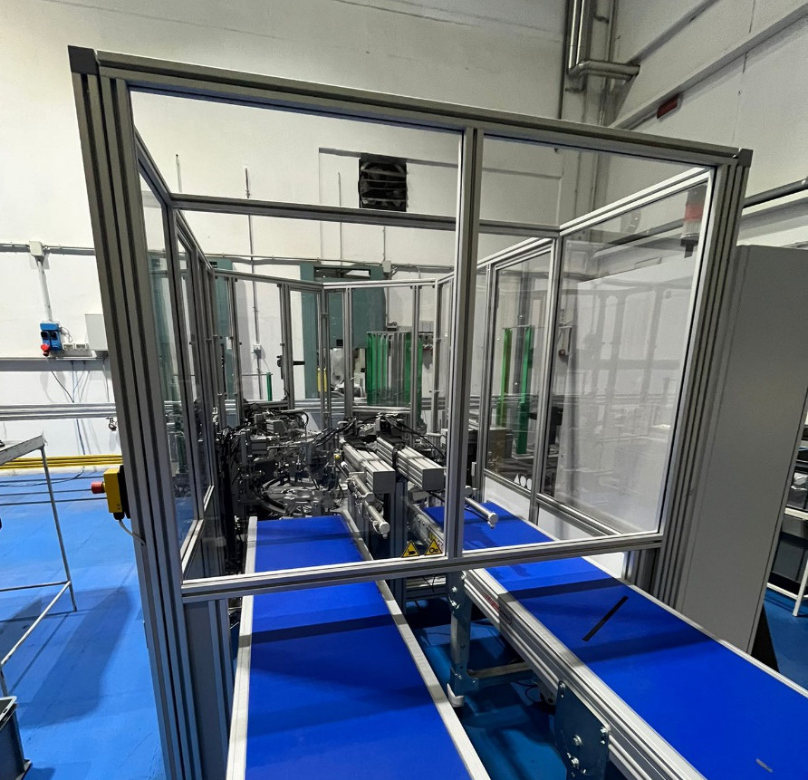
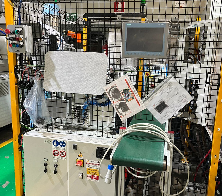
To assemble and test components with integration of various technologies: vision control, control with proximity sensors, leakage test, laser marking. In these work stations the handling is carried out by rotary tables or anthropomorphic or scara robots.
Welding Masks
We produce welding masks for our welding machines.
What’s new
The latest innovations in terms of technologies implemented are collaborative robots integrated with a vision system for recognition of the product, machining of parts with electro spindles on board of anthropomorphic robots.

100 automation projects are carried out every year.
A few examples of the last automation lines produced by Techpol’s customer:
"Vision control"
The robot picks up 8 parts at each cycle from the mold using a gripping hand. Deposits 4 components at a time on an electrical axis, which travels along a trajectory at a constant speed.
In the fixture there are 4 linear cameras and a profilometer.
As the components travel the cameras and the profilometer perform a scan.
They report the data on the "Alcon" software, which checks if the components are OK or NOK.
The data is reported to the PLC.
It will then be the PLC that will tell the robot whether or not to accept the moulded parts.
CUSTOMER: Tier 1
LOCATION: AT MOULDING MACHINE
Assembly, control and DMC laser marking
The robot picks up 4 parts at each cycle from the mold using a gripping hand. In the meantime, a Scara robot loads 20 bushings on centering pins placed on a fixture.
The anthropomorphic robot positions itself on the fixture.
By pushing with two pistons the bushings are pushed into the components with a force of 1000 kg.
The components with the assembled bushings are carried by the robot to a second bench which will check the presence of the bushings and perform the DATAMATRIX marking.
The dataMatrix marking guarantees the customer the following characteristics:
- ITEM NAME.
- DATE, TIME AND YEAR OF PRODUCTION AND ASSEMBLY.
Finally, a second robot will take the components from the bench and perform a scan of the DMC. In case of compliant components, they will be downloaded to the conveyor belt for final packaging.
CUSTOMER: OEM
LOCATION: AT MOULDING MACHINE
Automation for assembly and control
Once moulded, the components are unloaded by a 3-axis robot into shuttles.
The shuttles through the Montrac line are positioned in the various stations where the operator picks up the components and manually pre-loads the various feeding slots of the assembly line.
The machine is able to assemble 2 versions both simultaneously and individually, all with a cycle time of only 4seconds per part.
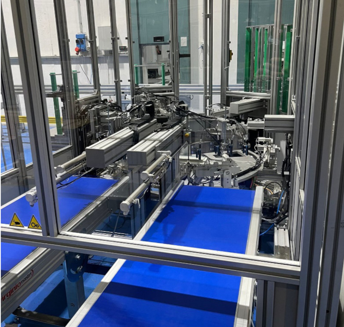
The automation consists of a rotary table, numerous pneumatic movements and correct assembly check sensors.
In the last station, a "pick & place" picks up the assembled components and checks correct assembly by means of sensors. If the components are compliant, they are downloaded onto athe conveyor belt where the operator will take the components from the belt to insert them in the dedicated packaging.
CUSTOMER: Tier 1
LOCATION: ASSEMBLY DEPARTMENT
Automation for drilling and threading
A 3.- axis robot picks the moulded part from the one cavity injection tool.
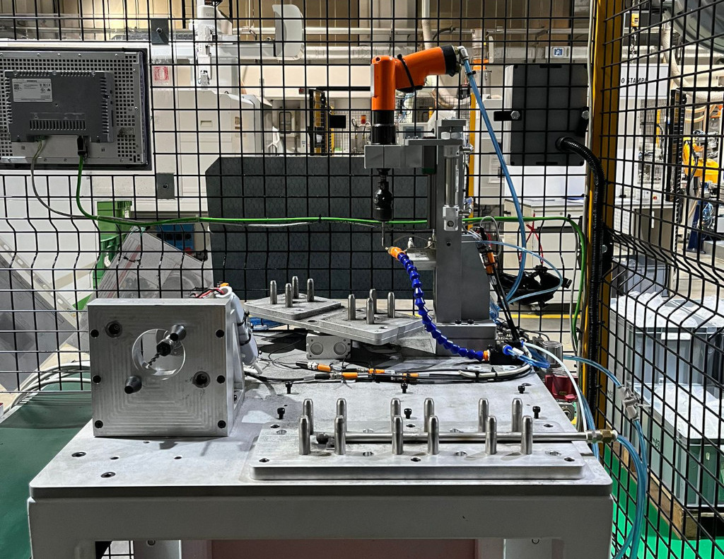
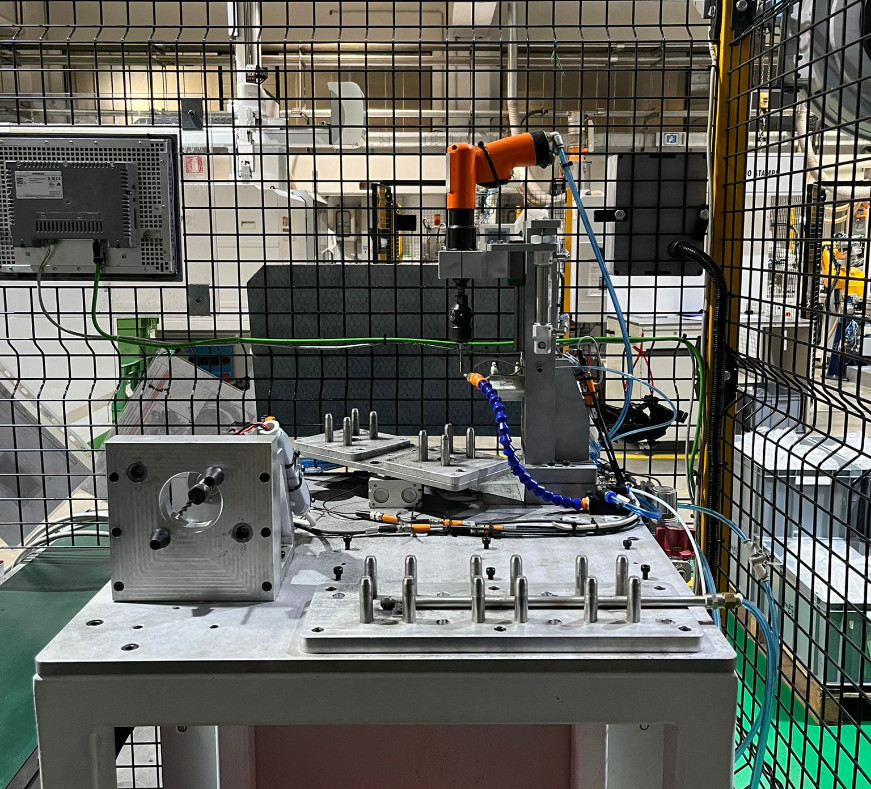
The component is taken to a bench where a drilling motor, moving forward, creates the hole in the molded component.
A quick coupling system has been inserted on the gripping hand, which comes into operation in order to make the hole in the best possible way.
The components are then placed on a rack to be cooled. The robot picks up the already cold component and takes it to a threading station.
Through a pneumatic system, the die makes the thread in the component. Once threaded, the component is picked up by the robot and unloaded onto the conveyor belt.
CUSTOMER: OEM
LOCATION: AT MOULDING MACHINE
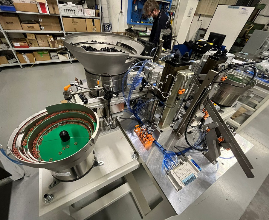
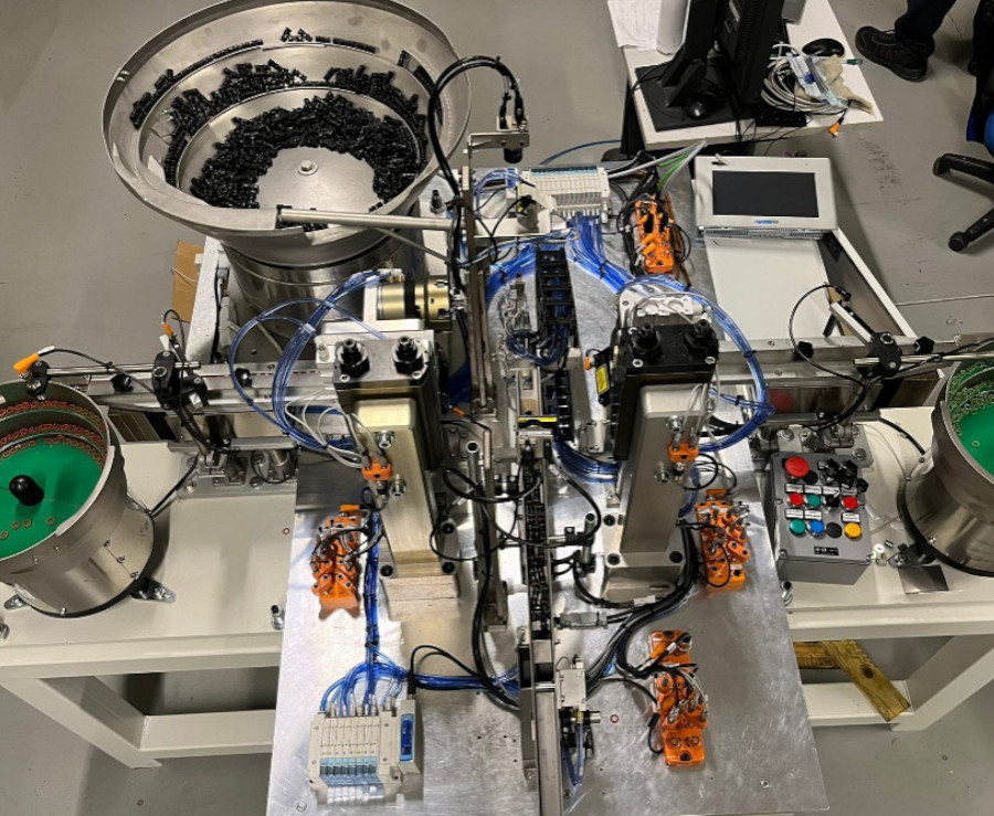
Automation for O-ring assy and control
The automation was designed and built in order to minimize the presence of the operator.
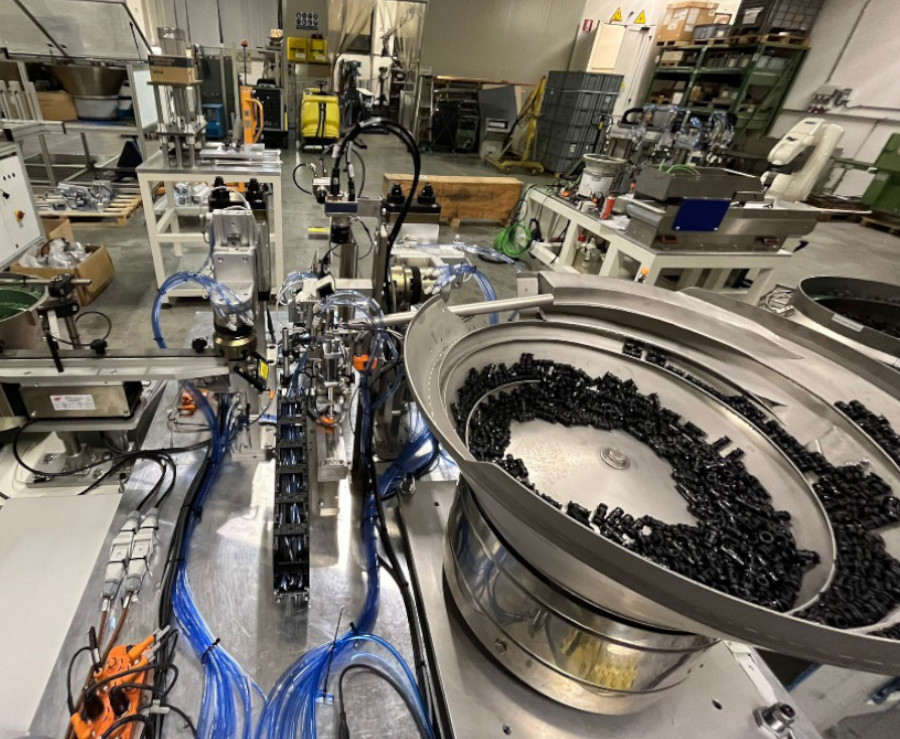
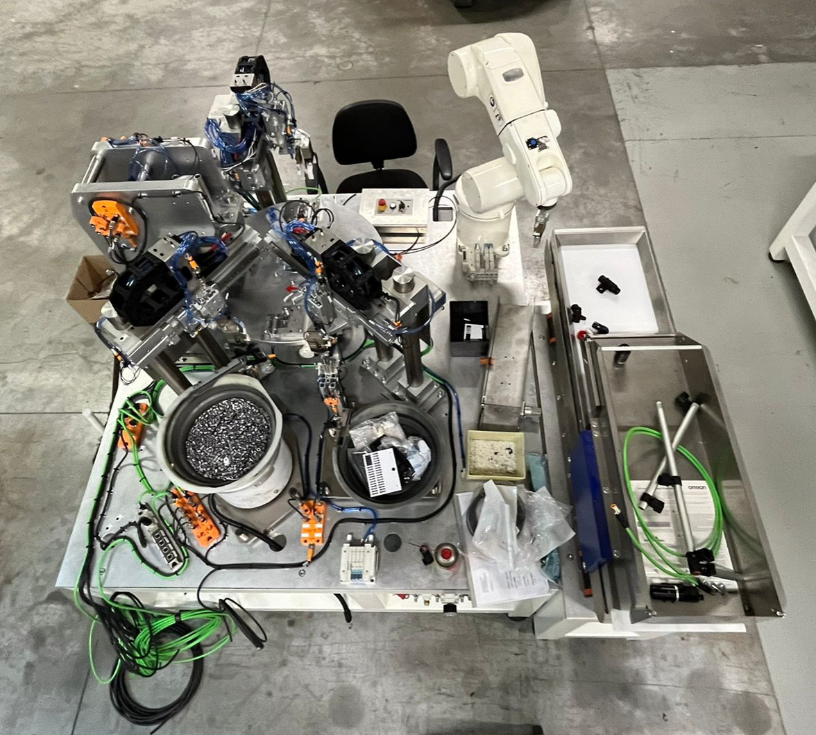
The machine is composed of vibratory feeders, pneumatic movements, electric axis and check sensors.
The operator loads the components and the o-ring into the vibratory feeders. The electric axis with a gripper and a rotating blade on board picks up the component. The direction of the component is checked by means of a camera. In case of incorrect direction, the vane rotates 180 ° in order to have the component in the right orientation.
The electric axis advances to an intermediate position where there are 2 pliers that assemble the o-ring on the component, one green and one red, by means of pneumatic movements.
Once the o-ring has been mounted, the electric axis advances to the final location where a second camera checks correct assembly: if compliant, it is discharged into a chute.
CUSTOMER: OEM
LOCATION: ASSEMBLY DEPARTMENT
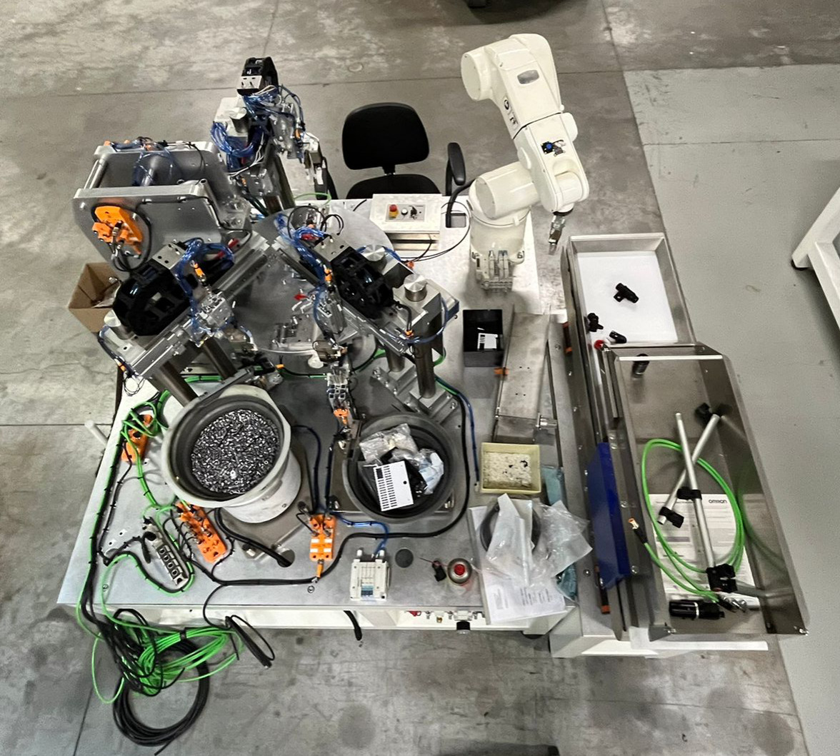
Automation for bushing assy and control
The operator loads the components on the hopper placed on the vibration feeder. The hopper, vibrating, brings some components into the pick-up area.
A camera located above the picking area tells the robot which component it can pick up. The anthropomorphic robot, through a coordinate system X, Y, Z, RX, RY, RZ picks up the components and places them on the rotary table.
The peculiarity of this automation is that it will be able to process 5 versions.
Placed on the rotary table the components are rotated to a "pick & place" position where the bushings are assembled on the components.
In the next station a press assembles the bushings by means of a pneumatic cylinder. The component is checked, if compliant, it is unloaded into a chute.
Customer: Tier 1
LOCATION: ASSEMBLY DEPARTMENT


